Quick summary: Get started in understanding the plan, sections, and elevation drawings with our complete beginner’s guide. Perfect for architects and designers, learn techniques to bring your ideas to life visually.
Plan, section, and elevation drawings are very basic requirements in all aspects of architectural design and construction, as they are the backbone of the project’s structure.
The instructional guide makes these important components for architectural drawings clear, beyond just lines on paper. They express the identity of the built environment as well.
An architect shapes an idea, and it is the schematic, section, and elevation plans that make the idea a scheme that can be studied, analyzed, and eventually built.
Every drawing puts forward new standpoints, and the union of different drawings allows a smooth development of the architectural process, from the first sparks of an idea to the last nail going in.
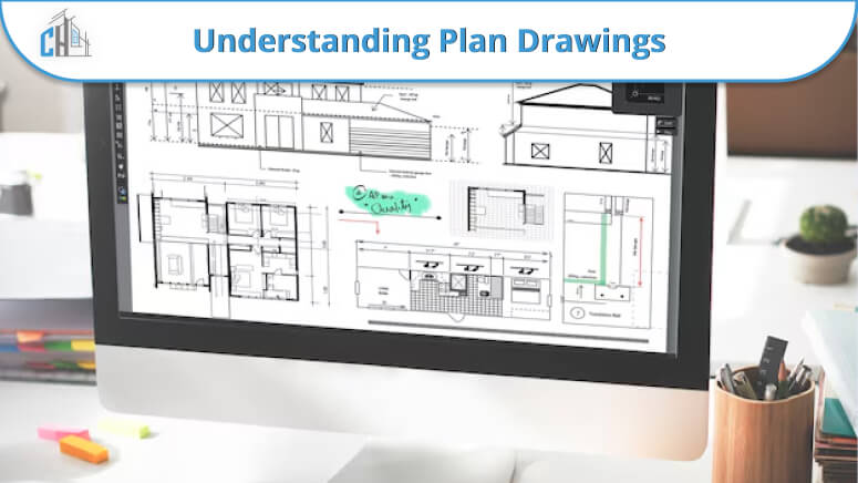
Understanding Plan Drawings
A plan drawing is a horizontal cross-section of the building, a view from top to bottom, which shows the floor plan of each level. To architects, these drawings are important for determining the room sizes and locations and also the relationships between spaces.
Plan drawings not only show the wall dimensions, layout, and room design but also indicate the location of fixtures, such as plumbing and electrical elements. Such drawings give essential designs of the whole building system and its operation.
Types of Plan Drawings
There are several types of plan drawings, each serving a unique purpose in the architectural and construction process: There are several types of plan drawings, each serving a unique purpose in the architectural and construction process:
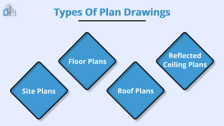
Site Plans: This is going to provide general information about my project, including the layout of spaces and buildings, landscaping, and any external features. Site plans are critical in this regard in that they are meant to clarify the link between the proposed structure and the environment in which it is located.
Floor Plans: Through pictures of the layout, the floor plans of a building display the design of each floor, showing the rooms, halls, entryways, and everything else. They pictorially play this vital role as they depict how free spaces are use.
Roof Plans: The last images show the roof, where the drawings will indicate the shape, roofing materials, slopes and drainage systems, which may vary depending on the type of roof used. Besides aesthetics, the roof plans are also used to achieve the many practical reasons for the building. Watershed needs are some of the aspects that should considered.
Reflected Ceiling Plans (RCPs): Such sketches try to show the ceiling geometry on the floor as if it is a mirror image of the same. RCPs are well-suited to demonstrate lighting, such as ceiling finishes and HVAC drawing. This is a critical function for design and usability as we try to achieve multiple system integrations with elapsed installation of ceiling appliances.
The different drawings used in the plan play a critical role in evidencing the architect’s vision while ensuring zero levels of confusion between all stakeholders in the design and construction.
The mission of the several stakeholder viewpoints shown here is to provide an understanding of the scale and details of a project, which helps to ensure a passage from concept to completion without too much hitch.
Common factors in plan drawings include
- Walls: Represented by parallel lines with a diagonal hatch.
- Doors and Windows: Shown as gaps in the walls.
- Stairs and Fittings: Represented by specific symbols within larger spaces.
Interpreting a Plan Drawing
To interpret a plan drawing correctly, one must understand:
- The conventions used for showing elements
- The scale, typically representative of one foot or meter per square on the drawing
- The direction of the view is usually indicate by compass points or the architect’s mark.
Read more: The Importance Of 2D Floor Plan Drawings For Architectural Design
What is a section drawing?
Apart from sections and elevations, a cut-through-section drawing, or rather, a much-heard colloquial name, depicts a building from the vertical perspective and thus enables the viewer to see its layers and components.
It cuts through building projects with slicing motion, unveiling the inner elements exactly as looking at the technical chromosome.
This depiction is not simply important in drafting structural systems but also in determining the necessary heights of floors and ceilings, dimensions of staircases, and the integration of supporting constructions such as beams and columns.
A Section Drawing is the designing of a drawing that accurately represents the interior, exterior, and other details of the house.
Section drawings are the main method used for architectural documentation, opening the view into places that are concealed when looking at plan drawings.
They make you notice the in-between spaces that are link to each other vertically and how the building is attach to its pedestal. Along with that, these drawings display technical questions like insulation works and foundations, and they will make sure of the safety and energy efficiency of the building.
Types of Section Drawings
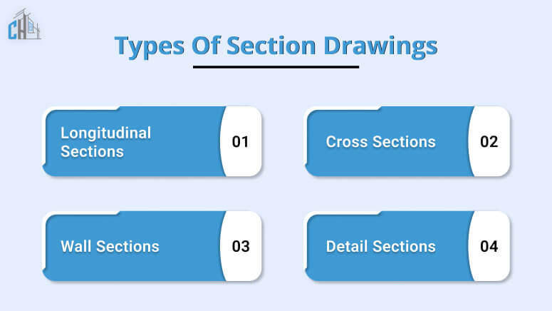
Longitudinal Sections: These are placed in the longest perpendicular part, enabling a side view that tends to illustrate height as well as internal and external facade dimensions.
Cross Sections: These planes are perpendicular to the earth’s rotational plane and are extremely useful in understanding the shape of the structure and reading the interrelation between the west and east sides of the building.
Wall Sections: Let us take a closer look at the prototypes of the walls themselves. What materials were use? It remains up to the structural engineers to explain the layers and components that hide behind them.
Detail Sections: Magnifying the image of the building by identifying areas to provide a specific view with all details regarding construction methods and materials at the magnified level.
All this can achieve through the use of section drawings, plan views, elevations, and other kinds of illustrations. These documents then become a set of comprehensive instructions for all phases of construction.
One of the numerous benefits of this design approach is that the final appearance of the built edifice is thoroughly clear to everyone who is involved in its creation process.
What is an elevation in architecture?
Raising building designs is like freezing a moment of a structure, and at other times, they even show the inside of a building, only showing a flat picture of just one side of it.
The elevations are created in scale versions to give us a true sense of the building’s appearance from any side – front, back, or side. While plans and sections allow us to cut the building into half and give a sneak- peek of the inside, the elevations are what we pay close attention to when the exterior look is the main issue, as they focus on details such as the materials used, the size of the structure, and the windows and doors.
They provide a chance to see how the indoor and exterior features – exterior finishes and so forth – come together so you’ll be confident once the building is finished. Hence, it will not just be helpful for construction team workers but also for clients with whom they can picture together how the structure can be set in the natural environment once it is finished.
Insight into Elevation Drawings
Elevations, or facades, are the external views of the building and are often use for presentation and design purposes to show how a building looks from different perspectives.
Types of Elevations
There are four main types of elevation drawings:
- Front Elevation
- Rear Elevation
- Right Side Elevation
- Left Side Elevation
Each provides a different external perspective.
Uses in Design and Presentation
Elevation drawings are critical for the following:
- Showing building detail and proportion
- Displaying the design in a way that clients and other stakeholders easily understand.
Integrating the Drawings in Architectural Practice
Aside from the theoretical impressions they create, the plan, section, and elevation drawings are irreplaceable instruments that architects apply.
Creating a Common Visual Language
This kind of drawing creates the mutual basis of communication between different actors in and outside of the building process.
Communicating Design Intent
In some cases, architectural drawings serve as a legal document that outlines the requirements, restrictions, and permissions for construction.
Best Practices in Creating and Interpreting Architectural Drawings
Construction and interpretation of architectural drawings entail parallel work in both artistic and scientific fields, an accurate balance of preciseness and creativity.
Accuracy is Paramount
Reproduction of the same dimensions, along with the elimination of errors to avoid costly mistakes in construction, are major priorities.
Consistent Use of Symbols and Notation
To prevent the appearance of complexity and inconsistencies, architects must integrate native symbols and notations within their drawings in a unified manner.
Regular Update of Drawings
Regularly updating the drawings with the most current changes from the design subcontract is of great importance to both the design and construction managers.
Conclusion
Architectural drawings are the heartbeat of a building project. Plan drawings, section drawings, and elevation drawings collectively provide a holistic view of the design intent, structure, and aesthetics of the project.
Chudasama Outsourcing offers excellent global outsourcing CAD drawing services, known for clarity and efficiency. It provides architects and firms support to improve their designs with great precision and speed. Accurate drawings showcase the firm’s commitment to design and urban planning.
The service is open to experienced architects, and anyone interested in architectural and construction drawings. It’s a chance to share your vision or CAD designs and join a larger community.