Quick summary: In 2025, understanding the types and importance of construction documents is essential for success. Learn more about them here.
Construction documents (CD) are the final documents consisting of specifications, materials, and other particulars, that are needed for understanding and implementing a building plan. They come into being during the final stage of architectural design during which the design is first developed, then bidding starts.
Architects – or engineers are typically those who do it. The CD is critical because it aids you in a permit to build and its details are for the construction of how it should be done. Usually, they are labeled in accordance with the United States National CAD Standard so that everyone knows what documents they should read at a glance.
In this post, I will cover what you need to know about the construction documents to include the 12 + most common types. I will also discuss their purpose and role in the design process.
What Are Construction Documents?
Construction documentation (CDs) is a detailed set of schematic drawings and specifications that describes the building process and the construction of the structure.
These documents act as a guide for the contractor and architect and the documentation is a way of communicating all the needed information that will be transformed from drawings into a physical form. Well-developed CDs give a clear view of materials used, structural methods, and aesthetics plans as well as the client’s vision so that the finishing project exceeds the client’s satisfaction and is in compliance with regulatory standards.
What is Construction Documentation?
Construction documentation is a process and a product of preparing accurate drawings, specifications, and reports dealing with buildings and/or structures. It is worth noting that this information base contains a variety of papers starting with architectural drawings, engineering plans, building specifications, contracts, etc.
This phase is critical since it facilitates the transition of the project design to actual construction so that each component is thoroughly thought of and provided for before the physical work begins.
The detailing of construction drawings is also often the key to the reduction of confusion and mistakes happening during the construction which, in turn, can also avoid delays and modifications of the original plan.
Also read: Understanding SD, DD, and CD in Construction: What Do They Mean?
Exploring the Significance of Construction Documents
Construction documents not only function as a blueprint for the building process but also act as a binding agreement between the client and the contractor. They encapsulate the design intent, project scope, and regulatory requirements, creating a shared understanding between all parties involved.
The significance of these documents cannot be overstated as they serve as a fundamental reference point throughout the project lifecycle, from bidding to the final construction phase. Ensuring precision within these documents is crucial as they are the definitive source for resolving any disputes that may arise, assuring a project’s integrity and finance management.
Types of Construction Documents
There are two things included in Construction Documents: Production & Drawings The construction documents are officially drafted per the standards requiring the reader to identify which among the many hundred pages of architectural drawings and specifications to look up where it belongs.
There are various categories of construction documents: Architectural, Structural Engineering, Mechanical Engineering, Electrical Engineering, Plumbing, Landscape Architecture, and Civil Engineering.

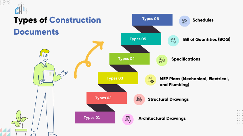
Within the realm of construction documentation, several key types of documents are universally recognized:
- Architectural Drawings: These include floor plans, elevations, sections, and detailed drawings. They visually detail the design of the structure.
- Structural Drawings: These schematics provide information on foundations, beams, columns, and other structural components, ensuring that a building can withstand appropriate loads and forces.
- Mechanical, Electrical, and Plumbing (MEP) Plans: MEPs are critical for outlining systems within the building, detailing the layout and installation guidelines for all mechanical, electrical, and plumbing components.
- Specifications: A written document that provides detailed descriptions of the materials, workmanship, quality, and standards to be applied to the project.
- Bill of Quantities (BOQ): An itemized list of materials, parts, and labor (with their costs) required to construct, maintain, or repair a specific structure.
- Schedules: This includes timetables for the project, delivery schedules for materials, and equipment installation schedules, which are crucial for project management.
- Addenda and Modifications: These documents record any changes or amendments to the construction drawings or specifications during the bidding process or construction phase.
1. Cover Page
Cover sheets/sheets in different colors display the project details, like the building name, the team members (owner, the designer, the engineer, etc.), the kind of structure, the site map, and the list of drawings in the cd set architecture. These pages are among the most important parts of the construction documents as they summarize all the details „glance at a glance”.
2. Site Map
This document gives a thorough layout plan of the site with many infrastructure units such as buildings, roads, utilities, etc. The site plan enables the contractors and other team members to clearly understand the legal requirements such as the access points, drainage, and landscaping prior to construction.
3. Demolition Plans
This sheet presents the existing state of the building, including the plan of the structure locations of the components that are to be demolished or removed, and the locations of the components that should be protected and preserved. It is important because it spans out items that need demolition and where they are located in order for correct construction and proper safety to be ensured.
4. Foundation Plans
The foundation plan drawings provide the image of the project (from above) in plan view showing the plan and location of the building foundation. These significant documents demonstrate the depth, location, as well as material used in the construction of the most vital elements like walls, columns, footings, and supporting members, through the use of floor plan symbols.
5. Floor Plans
This plan consists of the layout of each Floor plan for the architecture of the building, showing the door, wall, and door from the top of the roof. It will show how the rooms are connected and what kind of place is often used in a room.
The sketches are essential because they show the contractors/engineers what should be located in the building that is to be done. They just cannot leave the job of the real estate agents and prospective homeowners without visualizing the layout of the house to them.
Also read: The Significance of 2D Floor Plan Drawings in Architectural Design
6. Framing Plans
The drawing of the beam, column, or joist (the supporting elements holding the building’s roof or floor) is present on the sheet. The framing plan specifies the placement of the structural components following the positions of the loads to maintain stability and the required degree of engineering control.
7. Roof Plans
The roof plan is a way of depicting the location of the roof, shape, slopes, and location, including skylights and vents within. It’s necessary because it allows for roofs to be designed and built that meet both the requirements of drainage and aesthetics.
8. Exterior Elevations
On this sheet, you can see the building’s information on its exterior, details, and materials. It specifies the basic design elements (roof height, windows, doors, decks) to all parties contributing to the project. Additionally, it’s used for cosmetic assessment, which means that the building is examined from the outside point of view.
9. Construction of Walls and Framing
A sectional drawing is perpendicular to the structure, serves as a vertical “slice” and illustrates the elements of the structure. These documents remain significant because they outline the required dimension, method of execution, materials, and the method of construction for the installation of walls.
10. Interior Elevations
Sectional drawings of the interior elevation will depict the flat views of the finished interiors of walls- spanning floors, ceilings, decorations, and built-in furniture. Through interior elevation sheets you can see what information floor plans cannot show you, decorative trim, counters, outlets, switches, chandeliers, and fixtures, to mention a few.
11. Door and Window Elevations and Timetable
By these outline drawings, we can see the location of doors and windows as well as the design of these elements. The general spreadsheet is a schedule that has all the necessary products including the procurement of proper doors and windows for the construction project, and the installation by the construction site is coordinated.
12. Structural Details
The document outlines schematically the way to add the structural Steel detailing components like reinforcements, supports, etc. Since it will be used in the construction of load-bearing elements, it is essential because it enhances the accuracy in the construction process.
13. Mechanical, Electrical, and Plumbing (MEP) Plans:
The use of MEP sheets is for mechanical, electrical, and plumbing. The systems are highlighted in this sheet along with the installations.
Mechanical drawings: These mechanical drawings show the size and placement of all the mechanical equipment, the design of the ductwork, and the specification of various HVAC systems.
Electrical drawings: The electrical set of plans indicates the positions of all data outlets, power outlets, lights, and switches. They signify the right connection and boxes to handle the lighting along with possible other powering gear.
Plumbing drawings: Plumbing drawings indicate where the pipes are located and how large they are to bring clean water in and to carry waste away. They also display the vent risers that rise above the floor level allowing the sewer air to leave the building safely and without odor.
MEP drawings are critical for successful building construction as they guarantee that the mechanical, electrical drawing, and plumbing systems operate in a coordinated manner to make the building both safe and habitable.
Also read: Ultimate Electrical Drawing Services Handbook 2025
14. Specifications
This sheet gives out larger views of key areas of the building and design situations that are complex. Its importance lies in an elaborate description of building specifics which define precise instructions necessary for project implementation.
15. Permit Set
This is a central part of the CD that has data on the acquisition of building permits set in digital format. Models are often available in a package call sets. They include many different documents from the listed construction materials, one of them being a site plan, another, a foundation plan, and so on.
Each type of document is interdependent, collectively ensuring that construction projects are carry out to their specified requirements, within set timelines and budgets.
Also read: Understanding Permit Sets, Construction Sets, and Shop Drawing Sets: Explained!
Conclusion
The success of construction projects is highly dependent on the ease of managing Construction Documentation Services. Detailed documentation boosts communication, prevents delays, and ensures budget adherence. It assists in a systematic mode of construction, thus, transforming design innovations into reality.
Furthermore, it provides legal cover, defines rules in the beginning, and is a crucial part of the development of the construction industry.
CAD Drafting offers premier Construction Documentation Services: Providing top-notch Architectural CD Set & Drawing Set services, including Working Drawings, Presentation Drawings, and Permit Set provisions.


