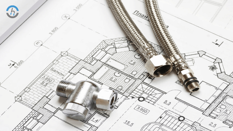
In the AEC building industry, mechanical drawings in construction documentation play a vital role for the workers on site who can understand the intentions and principles of the designer with more clarity.
Construction documentation consists of several drawings, such as architectural, structural, electric, plumbing, and mechanical drawings, and a final set of drawings detailing the construction details and the layout of the building materials.
These comprehensive diagrams encompass valuable information such as measurements, work plans, and visuals of the internal and external appearance of the building.
Mechanical drawing is a technical drawing of the machines. It represents components from different mechanical systems in the house, such as HVAC (heating, ventilation, and air conditioning). Usually, manila drawings consist of mechanical plumbing and electrical drawings, called MEP drawings.
The primary role of the mechanical drawings is to show in a correct way what each machine element’s geometrical characteristic is. This type of drawings contains several views of the product to depict its top, side, and other visual views.
These views are also sometimes called orthogonal projections or multiview drawings. Line projections show the vertical direction of the line in 3-dimensional objects when viewed perpendicular to the projection plane.
Mechanical engineers, drawing simply, discuss the problem, devise a solution, and define clear responsibilities. The drawings are the next stage after they are finished, and they are accordingly included in the construction diagrams, which are later applied for a construction permit. On the other hand, they are used to help analysts in the pricing of projects, too.
Moving denotatively, human drawings done by hand with the use of sketching elements such as a compass as their aid were the case in the past. The areas for drafting are provided with plain papers placed on slanting drawing boards.
Overview of Mechanical Drawing Definitions
Let us discuss mechanical drawings to contribute to construction before we uncover the subject: what are mechanical drawings? Actually, the easiest way to put mechanical drawing into tough words is that it shows how some objects and systems will constructed or manufactured visually. They draw attention to details, materials, processes, and other necessary definitions.
The Importance of Accuracy and Detail
Minor changes in mechanical drawings are just not acceptable because they take away the very essence of exactness. In a construction document, the drawing is supposed to give those who make the actual building the perfect image of what they will build. An error in just one component, no matter how small it is, could soon cause a series of other mistakes, which, in the long run, could be the very cause of a disastrous failure.
Types of Mechanical Drawings
When creating mechanical drawings, two types are considered: planning for construction drawings and various forms of mechanical drawings are assumed.
Manual Drawings
People still make manual drawings, which are drawings created by hand with experience that was developed and perfected over many years by architects and engineers. Whereas they are non-traditional, the drawings provide clarity and can remain an art form by themselves at the same time.
They may not be as flawless as people desire as they have these disadvantages: the amount of time it takes to make them and the impossibility of editing them.
Computer-aided Design (CAD) Drawings Drafting
The introduction of Computer-Aided Design (CAD) Drawings technology redesigned the sketching of mechanical drawings, allowing them to attain speed, accuracy, and adaptability, which manual drawings do not have any chance of beating.
2D vs.3D CAD Drawings
CAD can create not only 2D and 3D technical drawings but also geometric dimensions. 2D drawings, as contrasted with 3D ones, provide a standard presentation consisting of the x and y axis, while the latter adds depth and a third dimension – the z-axis – giving a better idea of what the product may look like when finally manufactured.
Pictorial vs.Orthographic Drawings
Pictorial drawings like the isometric or perspective views will help to illustrate the objective view of the project and make it feel like visitors are actually there. In engineering, we use orthographic drawings as the standard engineering views required for the most careful information.
Role of Mechanical Drawings in Construction Documentation
The mechanical drawings act as a universal language that connects the architectural designer and the on-site structural contractors.
The ability to provide an alliance with exact measurements and needs will significantly progress their capacity to ensure the right materials are available at the right time.
The major role of mechanical drawings is to render the dimensions and specifications of every element that is seen to on the specification sheet of mechanical components. The fine things that we want to make and those that are crucial for our ideas to work are, in fact, non-ne
Facilitating Communication
Through mechanical drawings, a complicated concept can expressed in a clear way that everyone in the architectural design and construction teams can easily understand, such as architects, engineers, construction managers, and laborers. Effective communication is a must, and the drawings of machines plus essence are need so that all parties in the project do the same thing.
Benefits of Using Mechanical Drawings
The advantages that mechanical drawings offer when used in construction documentation design are numerous and incredible.
Project Visualization and Development
Mechanical drawings give the customers full details of our objective. They enable a holistic approach, which means the possibility of discovering general problems beforehand and creating ways of solving them.
Improving Efficiency and Reducing Errors
Mechanical drawings help guide through die-building and, hence, reduce the error margin. Improvement in precision will result in a noticeable decrease in change orders and, in the process, make the construction timeline better and easier.
Technology in Mechanical Drawings
Today, the technical construction process widely uses technology not only for producing and applying working drawings but also for carrying out many other activities.
CAD Software in Designing and Editing
State-of-the-art CAD software is not a term for drawing only but design, analysis, and production. These devices help us change it from the beginning till the end.
Advantages of Digitalization
Digitalization Mechanical Drawings are one step further than the traditional way of representing because you can easily share and collaborate, giving an opportunity to involve BIM (Building Information Modeling) for more data-based visualization.
Reasons to Select Chudasama Outsourcing for Construction Documentation Services
Selecting Chudasama Outsourcing for your Architectural Construction Documentation Services will give your project a superb quality and execution and will be a good advantage to you at every stage of the project.
Our CAD specialists employ the latest technologies and have profound technical expertise to provide detailed technical specifications for construction.
We are dedicate to excellence, and all of our projects meet and surpass the highest industry standards while maintaining accuracy in the details. Our service automates construction, eliminates errors, and saves time and costs. Working with us means joining the team and achieving accurate and effective solutions.
Conclusion
Architecture mechanical drawings are a construction documentation tool, and through CAD technology, it has become a more useful and efficient tool than before. Enabling through the design and application of these illustrations in a project, engineers and construction staff can provide better precision and productivity.
The encouragement for industry practitioners is clear: if you opt to advance the use of mechanical drawings, you will have the machine shop know how to manage a professional and sophisticated project each time.


